Why melting “Pixels”?
Electron beam powder bed fusion (E-PBF) has taken large and important steps towards maturing for industrial use during the last decade. However, melting algorithms that make full use of the high scanning speed of the electron beam are underdeveloped.
Traditionally, the building process has been done using line melting: traversing the electron beam in parallel lines over the build area. This is mainly due to the simplicity of the implementation and the relatively predictable thermal behaviour during builds.
However, there are challenges when it comes to line melting, with one significant obstacle being the difficulty of automated build file creation. This challenge arises from the complexity of fitting lines onto intricate geometries while ensuring temperature control of the build.
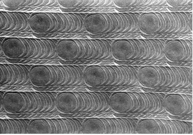
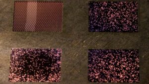
An alternative to line melting is spot melting, melting one spot at a time and then moving on to another. Freemelt is using diode electron guns which enable consistent spot size at around 200 µm up to very high beam currents, up to a maximum beam power of 6kW. The high beam current together with very short dwell times, moving the beam with a speed up to 4km/s, makes it suitable for creating discrete melt pools and can melt tens of thousands of spots in 1 second.
Importantly, spot melting can emulate line melting through melting points in a linear order. Thus, spot melting is more of a generalization of, rather than an alternative to, line melting.
This leads to an interesting property of spot melting: since the location of each spot isn’t constrained by some line, it’s much easier to approximate a given shape with points than with straight or curved lines. Thus, spot melting is well suited for automatic build file creation.
Spot melting has several other interesting benefits, read more about spot melting in general here.
Pixelmelt®
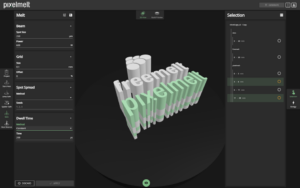
To facilitate spot melting, Freemelt has developed Pixelmelt®, a cloud-based software that, through automation, dramatically speeds up the process of build file creation and lets the user define his own process via free build parameters and spot spread algorithms.
Workflow
Build file creation using Pixelmelt® follows these stages:
1. Create a CAD file of the desired build and slice it into a .3mf file using compatible software
2. Import the .3mf file into Pixelmelt®, which will automatically divide every slice into uniformly spaced pixels
3. Apply various melt algorithms, beam parameters, grid settings, and with possibility to tag material, project notes etc.
4. Pixelmelt® will generate a complete build file with the chosen configurations
5. Load the build files into your Freemelt system and run the build
The cloud service model also ensures that user’s build files are easily accessed and are shareable within organizations, facilitating cooperation and project oversight. The cloud solution also enables accessibility from any device with an internet connection and the heavy calculations for the algorithms are done in the cloud. Without having to worry about the generation of build files, the user can fully concentrate on innovation and development.
Pixelmelt® gives the possibility to control each layer separately, if desired, and different parameters can be used for different objects.

Pixelmelt® Algorithms
Pixelmelt® outputs Open Beam Path (OBP) files, which is Freemelt’s data format that is used in Freemelt® ONE and eMELT®. The OBP-files contain timed-points, where each timed-point is defined by position, dwell-time, and beam parameters, such as beam power and spot size. Pixelmelt® provides several different spot spread algorithms and dwell time algorithms. The spot spread algorithms define the order in which the pixels should be melted for each layer and object. In each algorithm there are settings to adjust, giving the user full freedom and control over the build parameters. The software offers both ordered and randomized scanning strategies.

Pixelmelt® 2.0
Freemelt is now about to release a new version of the Pixelmelt®, Pixelmelt® 2.0. The updated version of Pixelmelt® gives the possibility to generate files for all process steps, including Start Heat, Jump Safe, Spatter Safe, Melt, and Heat Balance. The new version also includes new spot spread and dwell time algorithms, ProHeat® integration w/ sync points, rotations of the scanning directions, and shifting of the exposure order.

Conclusion
Pixelmelt® is a software for generating innovative beam scanning patterns in E-PBF. Pixelmelt® takes advantage of Freemelt technology with consistent beam quality at high beam power, short dwell times and the rapid movement of the beam. It enables full freedom and control for the user to get the desired material properties in every part of the build.
Additionally, the cloud service model ensures easy access and sharing of user’s build files within organizations, facilitating collaboration and project oversight.
Learn more about Pixelmelt® and Freemelt® ONE.
2024-02-27 14:18:51

